The first
schematic Design
|
-
Goals of this exercise:
-
Introducing the XiLinx ISE program
-
How to create a schematic source module
-
How to work with busses and single wires
-
How to create a new schematic symbol from a
module
-
How to assign package pins.
-
Test of the BASYS
or NEXYS2 kit.
|
|
Note: Lots of documentations for the ISE
can be found under the Help menu
 |
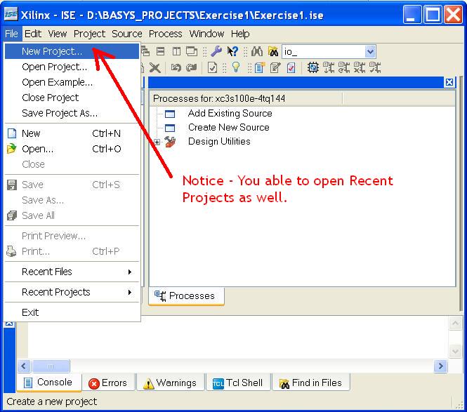
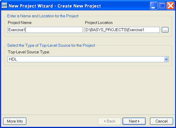
Creating a New
Project
|
| |
|
Please note -
Spaces
not
allowed in names and paths
|
| |
|
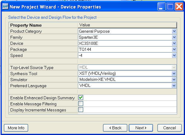
Selection for
the BASYS kit:
|
| |
|
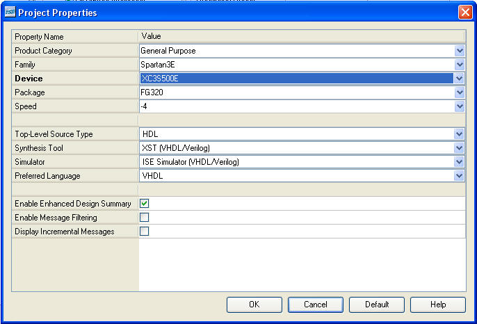
Selection for
the NEXYS2 kit:
|
| |
|
|
|
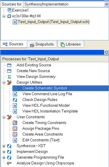
Creating New
Source - A Schematic
|
-
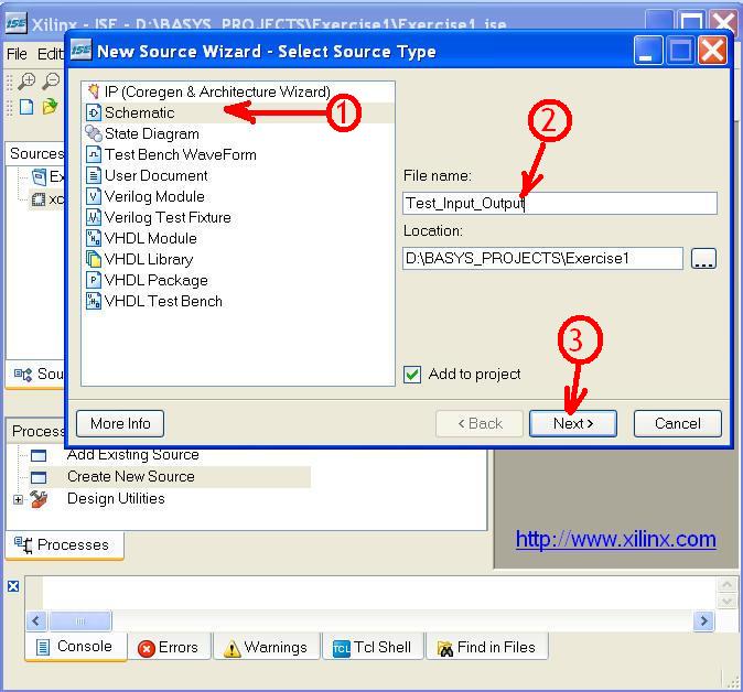
Schematic enables you to draw diagrams
with standard components (called symbols). A new symbol can be
created from a Schematic and later used in a new design.
-
Be careful to select names without spaces and
"non letter/digits" besides underscores.
-
Please notice! You will have to press Next
several times in order to actually create the Source file.
(Not shown here)
|
|
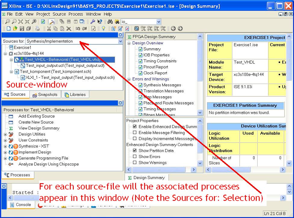
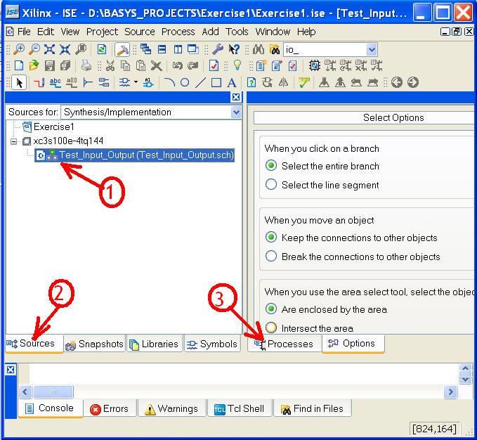
Select the
Schematic file for edit
|
| |
|
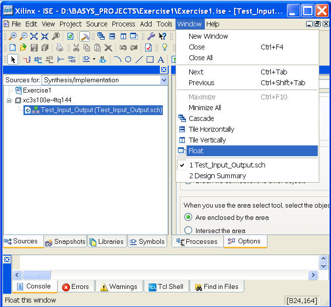
Use the window
- Float
(Much easier to work with the design)
|
| |
|
|
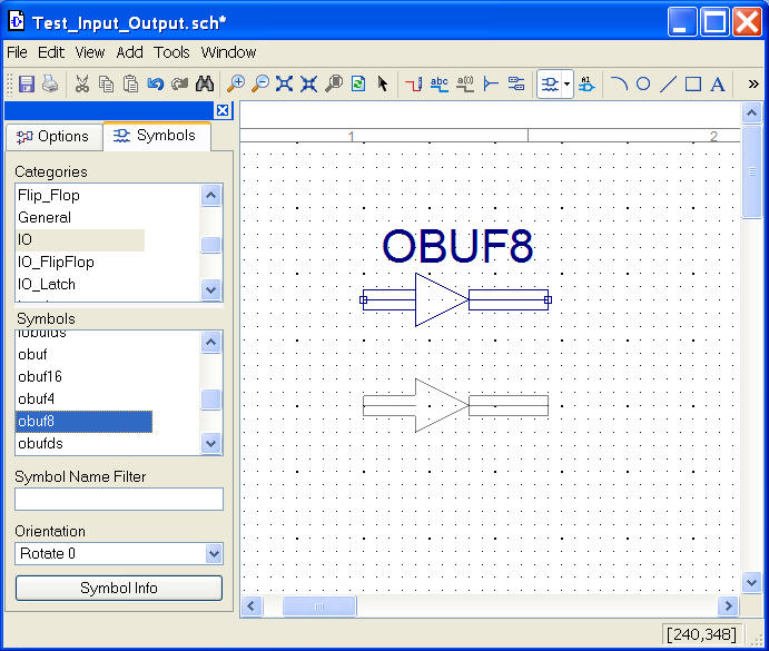
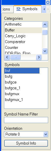
 Adding Symbols
 |
| |
|
|
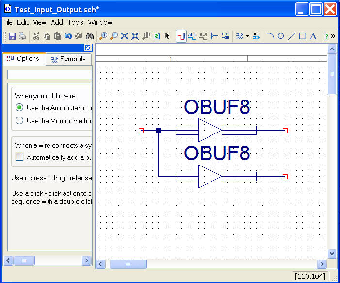
 Adding Wires and Busses
 |
| |
|
|
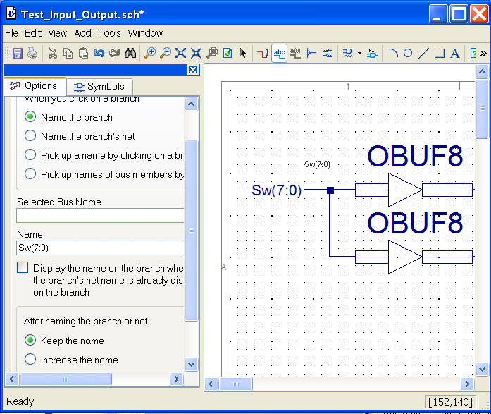
 Adding names to wires and busses
 |
| |
|
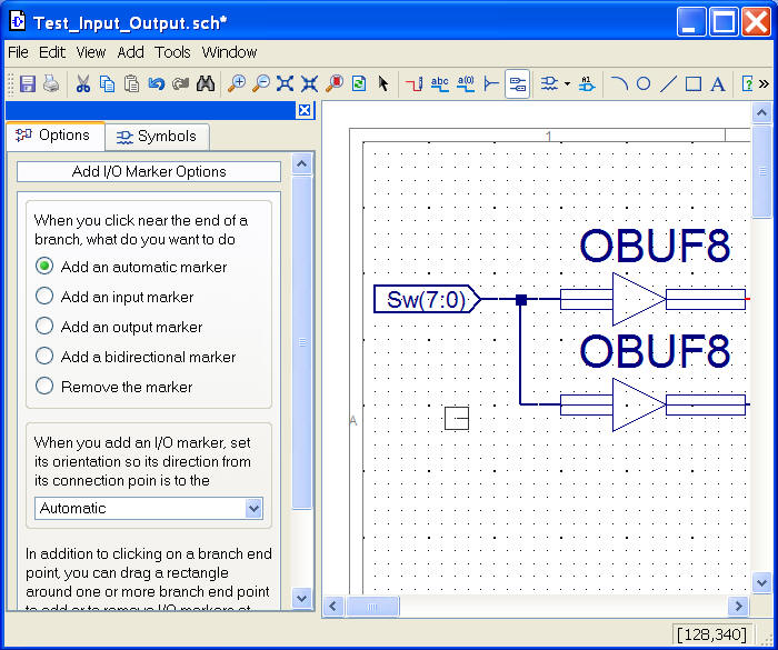
 Adding I/O
pads
Adding I/O
pads |
|
The a |
 |
|
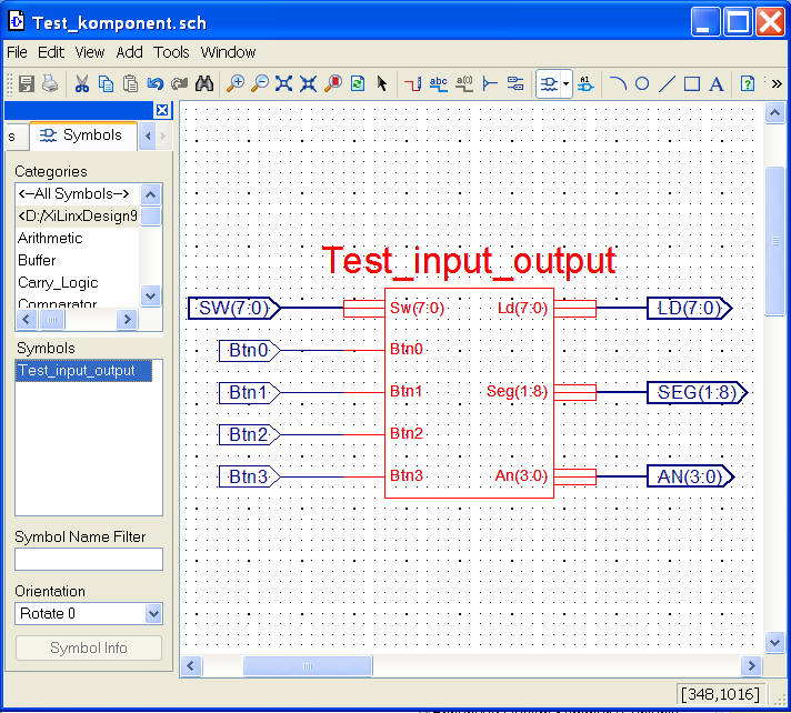
The Complete
design of the Exercise |
|
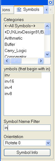
Use the filter
to search in All Symbols or use
the Categories. |
 |
 |
|
 |
|
|
|
How to
Create and use a new Schematic Symbol |
 |
 |
|
|
|
|
|
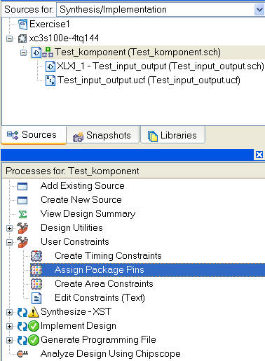
Assign Package
Pins for the BASYS kit -
(Details for the Nexys2 kit
below) |
|
Note the Tree-Structure of components
The first time will you be asked to add a UCF-file.
 |
|
|
|
|
|
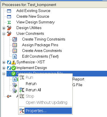
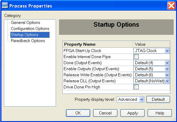
How to get
rid of the CClk warning |
|
|
 |
|
|
|
|
|
|
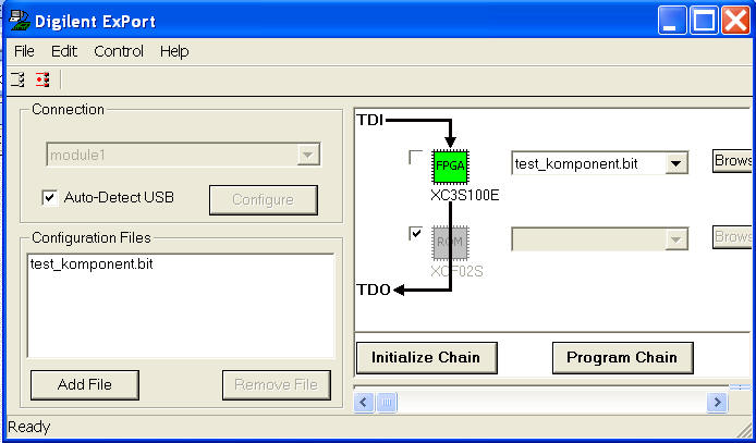
Use the
Digilent ExPort tool for programming () |
Press: (Initialize
Chain)
You must be able to find the bit-file (Add
File).
The program will remember the name and
placement.
Select the FPGA and eventually deselect the ROM.
Press: (Program Chain)
|
|
|
|
|
|
|
|
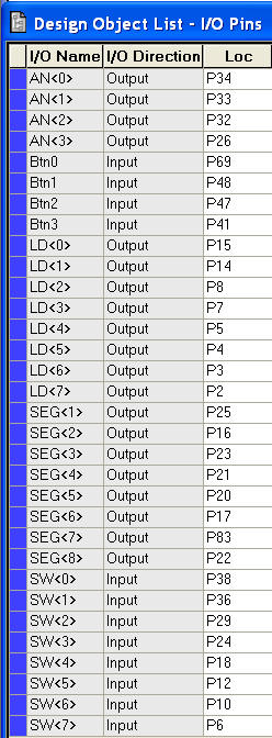
Pinout of the BASYS kit -
(extract only - please
consult the documentation for more details)
Note! add "P" to
the pin number
|
Test the BASYS:
Set switch 7 low and switch 6 to 0 high.
Press button 3, 2, 1, 0
Which levels turns leds and displays on/off?
|
|
|
|
|
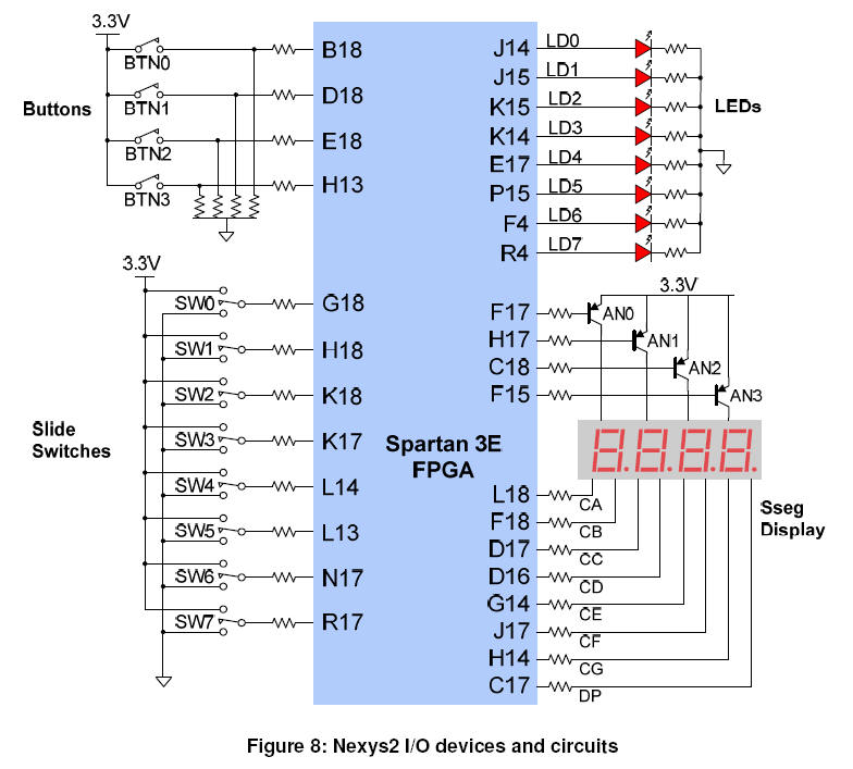
Pinout of
the NEXYS2 kit -
(extract only - please
consult the documentation for more details) |
|
|
|
|