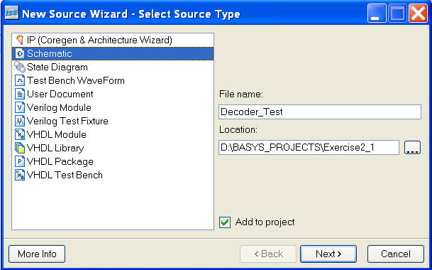
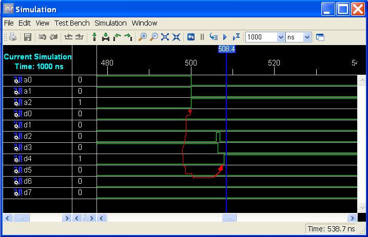
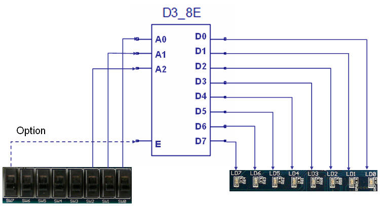
Decoder test -
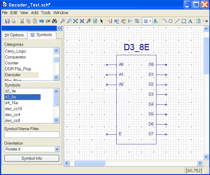
the D3_8E
|
|
|
|
|
|
|
| |
|
|
|
 |
|
|
 |
| |
-
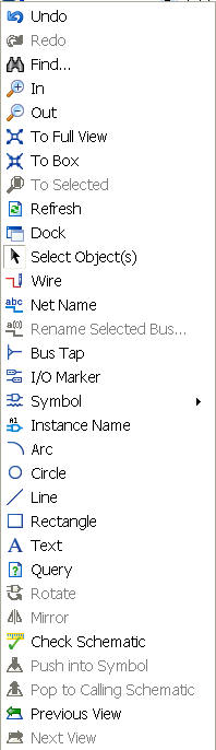
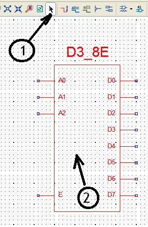
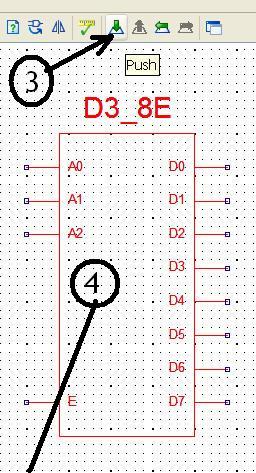
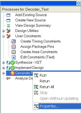
Use the [Select Object(s)] tool to point at the
component.
-
Note the red colour as marker
-
Select the [Push into Symbol] to open a new
window with the content of the symbol
(Works only with complex components like this)
-
If your working with floating windows must you
go back to the ISE window in order to find to Schematic.
-
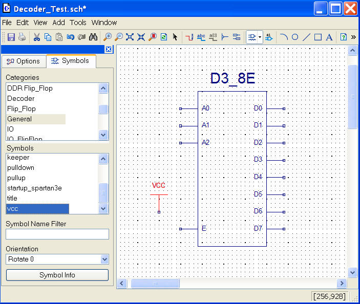
Try to figure the diagram
(which level of E will enable the Decoder)
|
|
|
| |
 |
| |
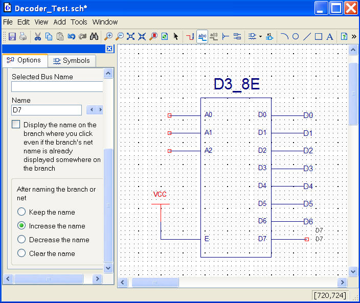
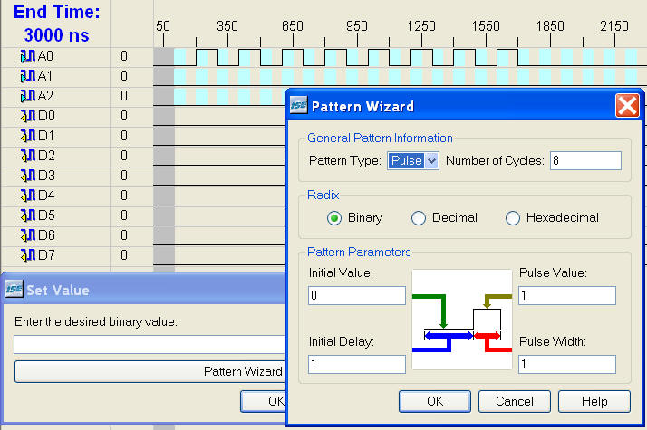
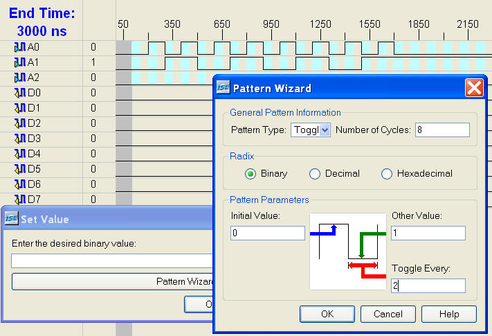
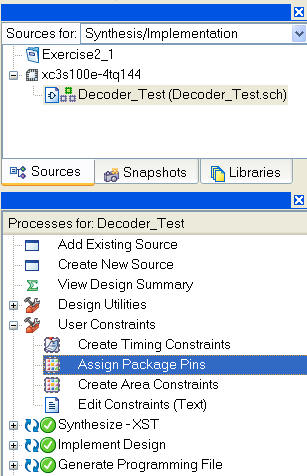
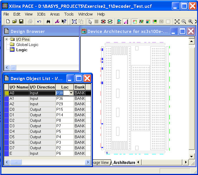
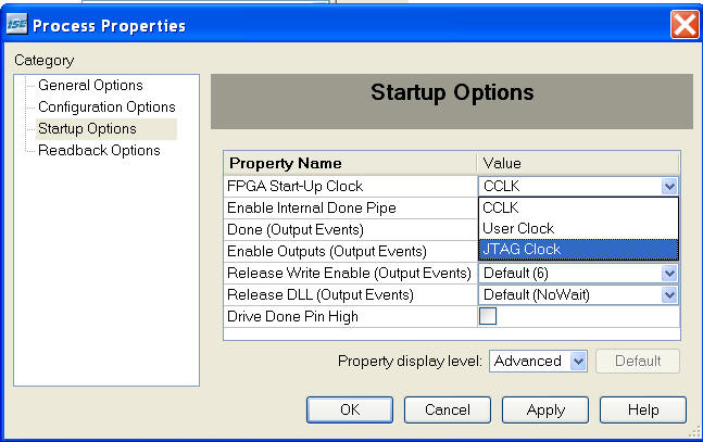
How to assign fixed
levels like 1/0 => Vcc / Gnd
|
|
| |
| |
|
| |
| |
|
| |
| |
|
|
|
| |
|
| |
| |
|
| |
| |
|
| |
|
|
|
| |
|
| |
| |
|
| |
| |
|
|
|
 |
|
|
|
| |
|
| |
| |
|
| |
| |
|
| |
| |
 |
| |
| |
 |
 |
|
| |
| |
|
| |
| |
|
|
| |
| |
|
| |
|
| |
|
| |
|
| |
| |
|
| |
| |
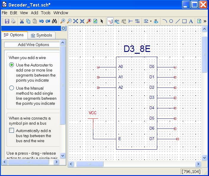
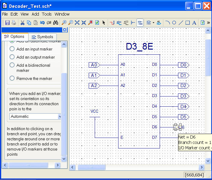
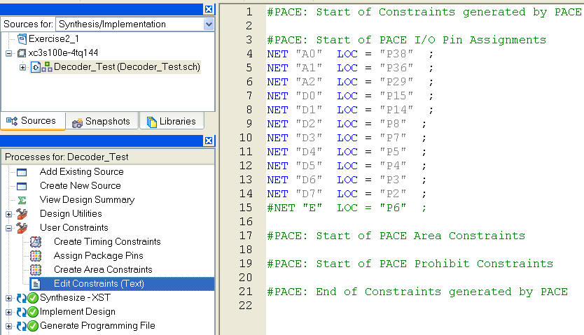
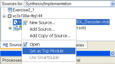
- Go back to the schematic and make the signal E an input.
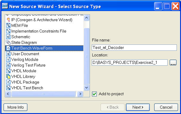
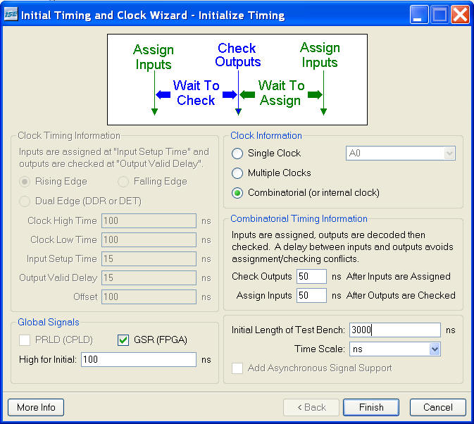
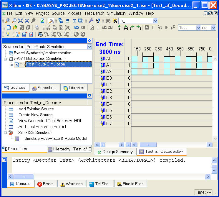
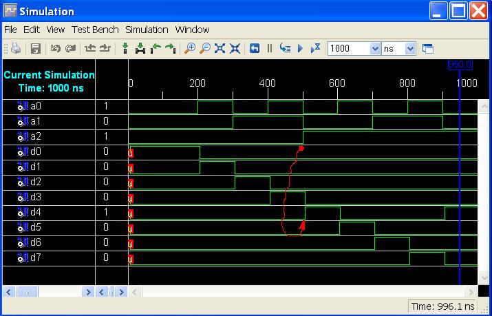
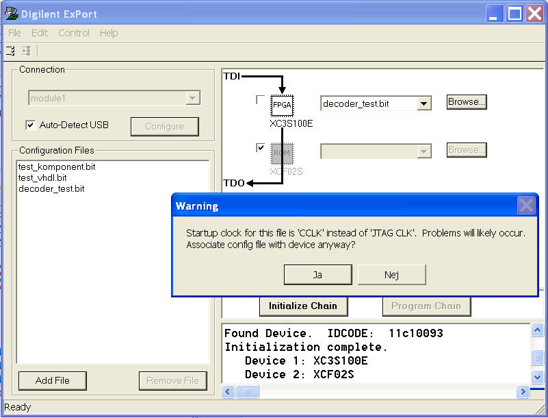
- Make a test with the new circuit.
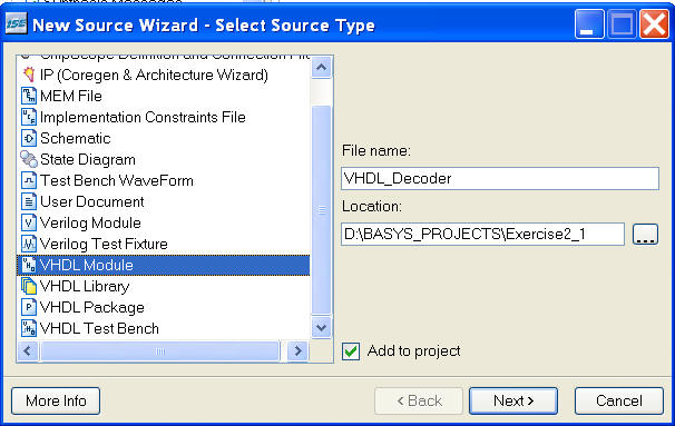
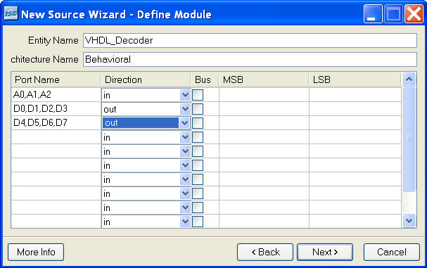
- If you like to try some VHDL - do the same with the VHDL
example.
|