VHDL Solutions - Concurrent
code
|
| |
|
Last updated:
08-02-09 |
|
|
|
|
 |
|
 |
| |
|
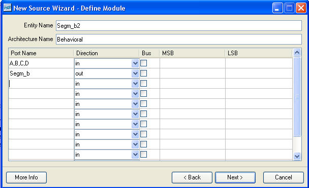
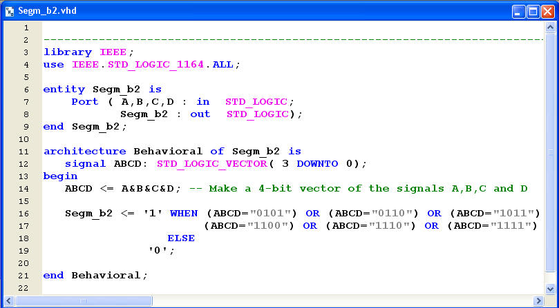
Concurrent VHDL:
WHEN .. ELSE
solution
|
|
|
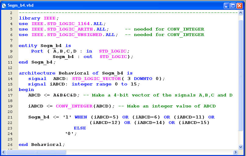
The basic idea in this solution is to
specify which combinations of ABCD should produce a
'1' at Segm_b2.Your allowed
to use more the one WHEN
statement.
A WHEN
assignment must always end with an
ELSE value.
You must specify a 4-bit value in
order to compare with ABCD.
Like "0101" for the value 5.
If your convert ABCD to an integer
value can you omit " "
|
 |
|
|
|
STD_LOGIC_VECTOR to
integer conversions
|
|
|
The VHDL type
integer makes it possible to omit the " " and
use decimal numbers instead.
If the range
0 to 15 omitted will
the default be a 32-bit version of signal iABCD
|
|
|
 |
| |
|
| |
|
| |
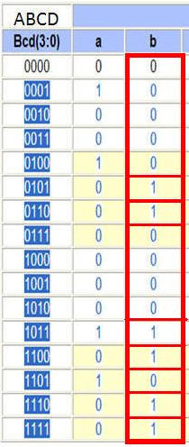
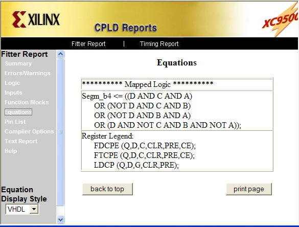
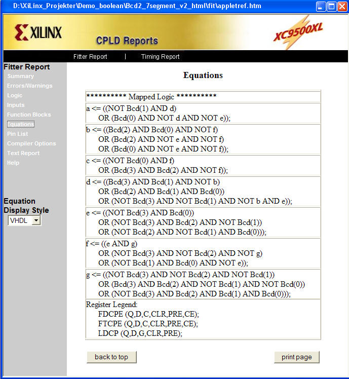
Please note:
No matter which VHDL solution you might chose will
the result be the same - as the Equations shown
above.
|
|
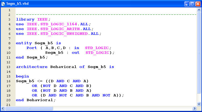
Concurrent VHDL:
The Boolean solution
|
|
|
|
Your allowed to use STD_LOGIC signals
directly in Boolean
expressions.Your might
however be forced to use parentheses for the AND
statements
|
 |
| . |
|
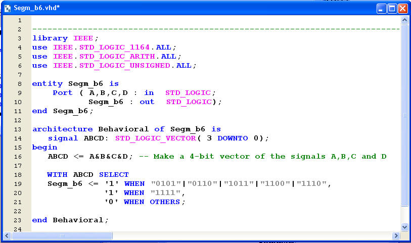
Concurrent VHDL:
WITH .. SELECT solution
|
|
|
|
Concatenation
ABCD <= A & B & C & D simply creates
a 4-bit vector of the four signals A,B,C,D.
The WITH
ABCD SELECT a nice way
to implement a truthtable for the Segment b
Please note! You will properly
always need a statement like
WHEN
OTHERS to complete.
The true even if you believe to
have specified every combination of a
STD_LOGIC -
VECTOR.
How come? (Hint! how many values can a
STD_LOGIC signal have)
|
 |
| |
|
|
Concurrent VHDL:
WITH .. SELECT solution
- Complete Bcd to 7-Segment decoder
|
|
|
|
|
|
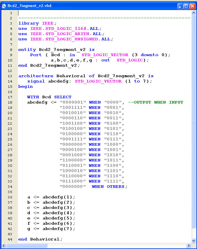 |
Splitting a VECTOR to Signals
When specifying a STD_LOGIC_
VECTOR is you allowed to use a
Low# to
High# or High#
downto Low#
specification.
The interval you specify will be
used from left to right and hence will:
a <= abcdefg(1)
b <= abcdefg(2) ... and hence fort for a
STD_LOGIC_ VECTOR( 1
to 7) spec.
|
|
|
|
The Boolean equations for a Bcd
to 7-Segment encoder
|
| |
Conclusion for
the VHDL solution:
The reason why a CPLD family
was chosen for this job is the fact that your
allowed to watch the Boolean Equations which
comes as a result of the Synthesize program.
If you compare this solution
with the one given by the Schematic will you
learn that by specifying a design. Please note
that even Segment a now appears to use very
little logic - compared with our own "handmade"
solution.
Even a skilled
engineer will have "a mission impossible" using
Carnaugh maps.
He can't take advantage of the internal
structures of CPLD.
|
| |
 |
|
|
|
|
|
|
|
|
|
|
 |