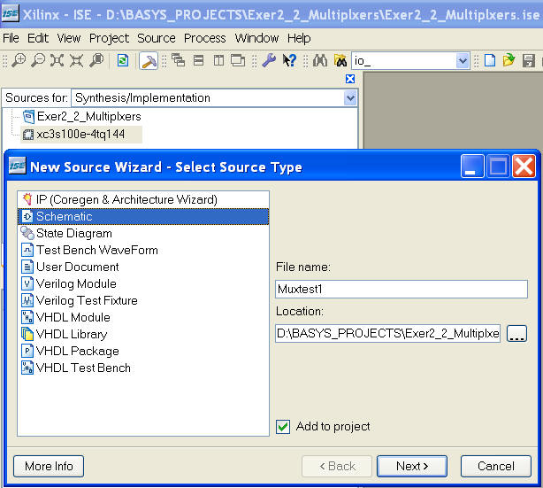
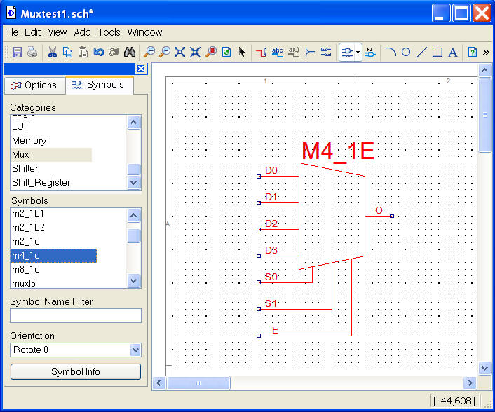
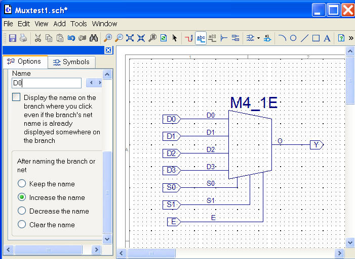
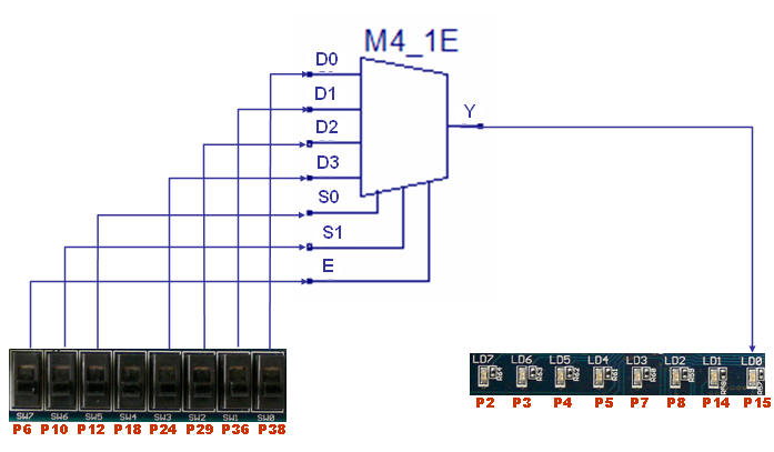
Multiplexer test -
the M4_1E
|
|
|
|
| |
|
|
|
| |
|
| |
Symbol info
For each symbol in the
schematic library exist a datasheet with a complete description.
You can find the Data book
with all datasheets under the help or you can get information
for the particular symbol.
VHDL information: The
components can be used from a VHDL based design as well
(More about this elsewhere)
|
 |
| |
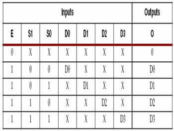
Extract from the M4_1E
Datasheet |
|
|
The Diagrams which used as description of
the M4_1E.This design element
is inferred rather than instantiated.
Oversat til dansk!
Dette diagram antyder kun princippet i kredsen.
I virkeligheden er den lavet på en anden måde
|
|
Logic in a FPGA
All combinatorial logic will be
implemented as LUT (Look Up Tables)
|
|
| |
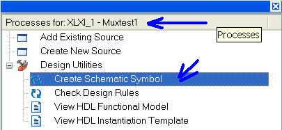
In older version of the XiLinx ISE was it
possible to implement and simulate a diagram like this directly.
Due to the fact that a symbol like the M4_1E build of M2_1
multiplexer is this not possible anymore.
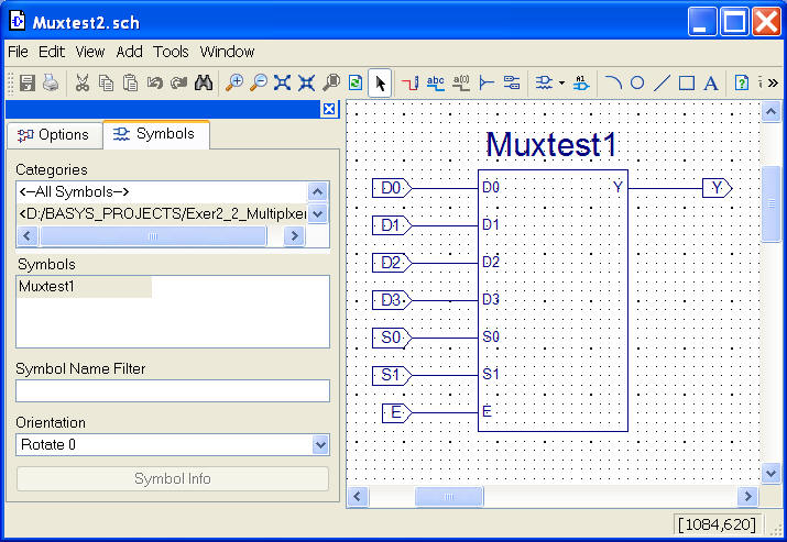
Instead do you have to Create a new
Schematic Symbol from the diagram and this can then be used for
implementation etc.
VHDL note: Nearly
everything in a design (including schematic diagrams) will be
translated to VHDL source files.
Will be presented later.
|
|
|
|
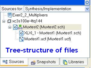
After selecting the Muxtest1 and by
pressing [Create Schematic Symbol] under the Design Utilities
will the Muxtest1 symbol be ready to use in a new diagram.
Note the tree-structure which present the
relation between the symbols.
|
|
| |
|
|
|
 |
 |
| |
|