| |
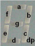
The four seven segment (+ decimal point) at the
BASYS kit must be used in a multiplexed manner where only one
display ligth up during the cycle. (Read more in the BASYS
documentation) The first step in order to create
a multiplexed display driver will be the Bcd to 7-segment driver
(actually a Hex to 7-segment driver)
|
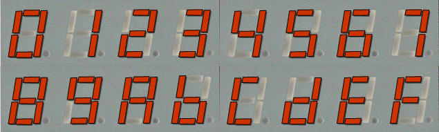
1a)
Fill out the Truth table below
1b) Choose a strategy for
the solution like:
>> Implement the min. term. equations
for each segment
>> Reduce the Boolean with Carnaugh
charts
>> Consider using a 1 out 16 Decoder
+ some logic
>> VHDL could be a solution ... but
maybe its a bit early for this
1c) Implement the solution
and test it on the board. The solution can
be downloaded and tested with this file if you like:
Test_bcd27segm_ver1.bit
|
 |
| |
Segments |
|
Bcd(3:0) |
a |
b |
c |
d |
e |
f |
g |
| 0000 |
0 |
0 |
0 |
0 |
0 |
0 |
1 |
| 0001 |
1 |
0 |
0 |
1 |
1 |
1 |
1 |
| 0010 |
0 |
0 |
1 |
0 |
0 |
1 |
0 |
| 0011 |
0 |
0 |
0 |
0 |
1 |
1 |
0 |
| 0100 |
1 |
0 |
0 |
1 |
1 |
0 |
0 |
| 0101 |
0 |
1 |
0 |
0 |
1 |
0 |
0 |
| 0110 |
0 |
1 |
0 |
0 |
0 |
0 |
0 |
| 0111 |
0 |
0 |
0 |
1 |
1 |
1 |
1 |
| 1000 |
0 |
0 |
0 |
0 |
0 |
0 |
0 |
| 1001 |
0 |
0 |
0 |
0 |
1 |
0 |
0 |
| 1010 |
0 |
0 |
0 |
1 |
0 |
0 |
0 |
| 1011 |
1 |
1 |
0 |
0 |
0 |
0 |
0 |
| 1100 |
0 |
1 |
1 |
0 |
0 |
0 |
1 |
| 1101 |
1 |
0 |
0 |
0 |
0 |
1 |
0 |
| 1110 |
0 |
1 |
1 |
0 |
0 |
0 |
0 |
| 1111 |
0 |
1 |
1 |
1 |
0 |
0 |
0 |
|
|
|
Truth table for the bcd27segm version 1 |
 |
|
|
|
Next step: Download this bit-file
top_muxdisp_ver1.bit
to your computer and then try the following..
Set switch 7:0 like this "0001 0010" or what you like to try,
press and release Button 3 in quick sequences.
1d)
Create a new version of your design, which
implements the same multiplexed functionality.
|
| |