|
Hint! Press the
<Ctrl> key and use the wheel on your mouse to adjust the font-size |
|
Combinatorial logic |
|
AND-OR logic |
|
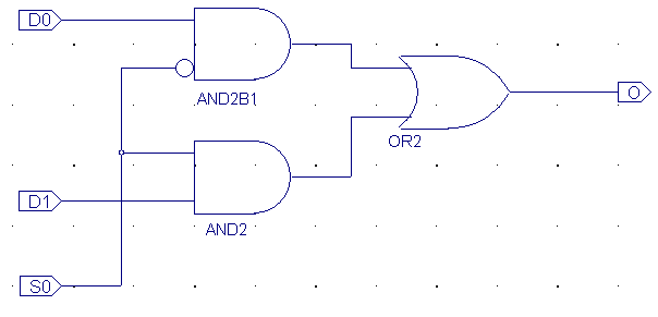
| The logic-functions
NOT, AND, OR can be used to form your digital design
Actually are all you need, NAND gates
Output = D0 ● /S0 + D1 ● S0
= /( /(D0●/S0)●/(
D1●S0)) |
|
|
Standard functions |
The
Multiplexer |
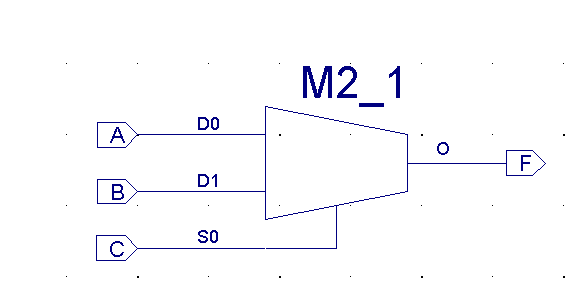
| Instead of creating
all logic from scratch, with AND-OR logic, will it be useful to work
with Standard functions like Decoders and Multiplexers |
|
| Function table - M2_1 |
| S0 |
Output |
| 0 |
D0 |
| 1 |
D1 |
|
|
Sequential Logic |
|
Asynchronous feedback loops |
|
| A combinatorial
circuit may (normally) not contain Asynchrony feedback loops.
However is sequential logic based on this type of feedback loop |
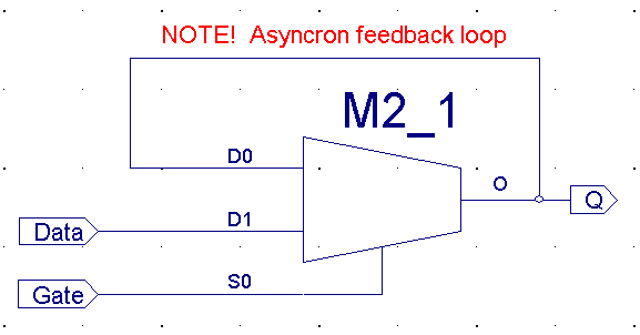
Note: Don't use this in
"real-life" projects.
Even it works
correct in the exercises |
| |
Gate
Data |
| Q |
00 |
01 |
11 |
10 |
| 0 |
0 |
0 |
1 |
0 |
| 1 |
1 |
1 |
1 |
0 |
| |
Q* = Next
value of Q |
Red values 0/1
are stable
|
|
D-Latch |
|
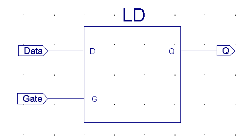
| The D-Latch seldom
used in State-Machines, more often will it be found in computersystems
used to de-multiplex a multiplxed Address / Data-bus |
|
A D-Latch level trigged (0 or 1)
In this case, active high (1-trigged)
|
|
D-Flip/Flop principle |
|
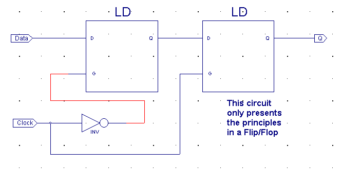
| If an active low
and an active high D-Latch connected serial (like shown) will an
edge-trigged circuit be formed. The first (Leftmost)
D-Latch will be open when Gate=0 and the rightmost D-Latch will be
closed.
Whenever the Gate change value from 0 >1 will the
Data value be transferred to the output Q.
If Gate = 1 will the value be kept stable on output
Q.
Question: What happens when Gate changes from
1 > 0 ? |
|
|
D-F/F |
|
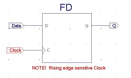
| D-F/F's are trigged
at level-shifts opposite the D-Latch which opens at specific level.
D-F/F's which trigged by 0>1 shift called positive-edge trigged.
D-F/F's which trigged by 1>0 shift called negative-edge trigged. |
|
| Clock |
Q |
| 0 |
Last Q |
| 0 >1 shift |
Data |
| 1 |
Last Q |
| 1 >0 shift |
Last Q |
|
|
State-machines |
|
Synchronous State Machines |
|
|
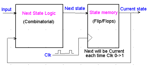
State-Machines contains a memory which remembers the
Current state.
The Next State Logic generates a new value for the
State memory - Next state, from the input values and the Current
state.
Each time the Clk make a 0>1 change will the Next
state become Current. |
|
|
Standard Sequential Logic |
Counters and Shift registers |
|
CPU |
"Just" a State Machine designed
to execute a program. |
