| |
In order to take advantage of the Display at the
BASYS / NEXYS boards do you need a Multiplexed display driver, and its a
good way to start using the kit and learn about digital design
and VHDL. The following solution made with
standard hardware symbols and not optimal in any way. Your task
will be to understand the principles and create your own VHDL
based components. Finally will you be able to
make the complete "single" VHDL-component for the driver
|
|
|
|
|
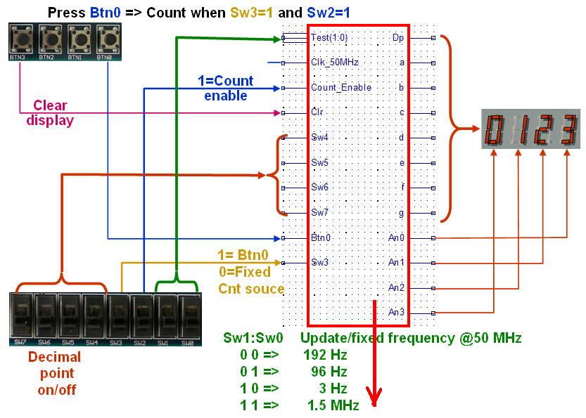
Try different combinations of Switches and
button presses:
Start with
Sw1:Sw0 = 00, Sw2=1,
Sw3=1 -
Press Btn0 several times - Press
Btn3 once - what happens?
Change to
Sw3=0 ..... and later Sw1=1 ...
explain what happens.
|
|
|
 |
| |
|
|
|
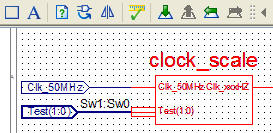
Clock scale ver.1 |
 |
Clock_scale_ver1
combines a 16-bit and a 8-bit counter to form a
24-bit counter - Q(23:0) = QH(23:16) &
QL(15:0)
The Test(1:0)
inputs = Sw1:Sw0
used to select among 4 different
frequencies.
|
|
|
clock_scale_ver1 |
 |
|
|
The standard clock-frequencies of the BASYS boards
can be selected among 25MHz, 50MHz and 100MHz with the jumper
(please check the documentation). The NEXYS2 board fixed
at 50MHz.
In order to reduce the rather high frequency
(say 50MHz) at least 18 F/F needed to form a scale-counter. Two
standard counters selected to form a 24-bit counter.
|
|
Counter w. 2-bit |
 |
In order to "multiplex" the multiplexed display we need a 2-bit
counter.The optimal clock frequency would be 200 Hz
(but higher will do as well)
The output sequence at S1:S0 will
be: 00, 01, 10, 11, 00, 01 .....
|
|
| |
|
Count2bit |
 |
 |
|
|
|
A 2-bit counter needed for the multiplexer /
decoder and its driven by the downscaled clock (Clk_200hz).
Note
how this counter formed with two Toggle-F/F's and each T-F/F based on
a D-F/F and a XOR gate.
|
|
|
|
Multiplexer 4-bit x 4 and 1-bit x 4 |
 |
You wont find a 4x4-bit multiplexer
as a standard component, hence must it be formed by
standard 1-bit multiplexers - and four
M4E_1E will do nicely.
The multiplexer for the Decimal Point
will however fit nicely into a
M4E_1E.
|
S1:S0 |
Y |
Dp |
|
0 0 |
Bcd(
3: 0) = A |
Dp0 |
|
0 1 |
Bcd(
7: 4) = B |
Dp1 |
|
1 0 |
Bcd(11:
8) = C |
Dp2 |
|
1 1 |
Bcd(15:12)
= D |
Dp3 |
|
|
|
| |
 |
|
|
|
Decoder 2 to 4 (active low) |
 |
|
S1:S0 |
/D0 |
/D1 |
/D2 |
/D3 |
|
0 0 |
0 |
1 |
1 |
1 |
|
0 1 |
1 |
0 |
1 |
1 |
|
1 0 |
1 |
1 |
0 |
1 |
|
1 1 |
1 |
1 |
1 |
0 |
|
|
|
D2_4E |
 |
|
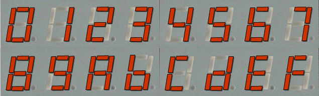
Bcd to 7-sement decoder ver.1 |
|
|
|
bcd27segm_ver1 |
 |
|
|
Read more about Bcd to 7-segment
decoding
here.
|
|
Now lets try VHDL |
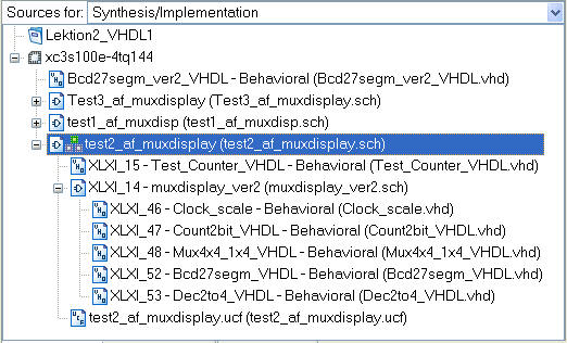 |
The VHDL modules which can found in the
tree-structure below "Test2_af_muxdisplay" mostly
empty source-files with only the Entity and some
comments etc.Please try to create your own code -
the teacher will give you hints.
|
|
| |
 |
|
|
 |
|
|
| |
|
|
| |
| |