SR-Latches not that often
used in digital designs - but they very important in concern
with PLC programming.
|
|
|
Combinatorial loops a must
in order to make sequential circuits, but at the same also very
difficult to handle in "real-life" systems.
In order to make those loops must you be sure to handle:
1) Hazard - Not allowed.
2) No critical races in the circuit.
3) No timing hazard either.
(More information
can be found in Wakerly 4ed. Chap. 7.10)
The shown implementations
of Latches so "simple" that they will work in pratice.
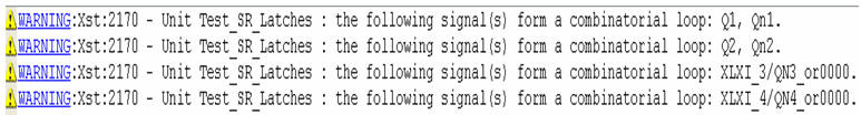
But the ISE will warn you
about the loops
|
 |
|
|
 |
|
|
Basic implementation of a
SR-Latch with NOR-gates.
How many Feedback loops can be found in this latch?
Read more in
Wakerly 4ed - 7.2.1
Or read more in
Mark - 6.1
|
|
|
|
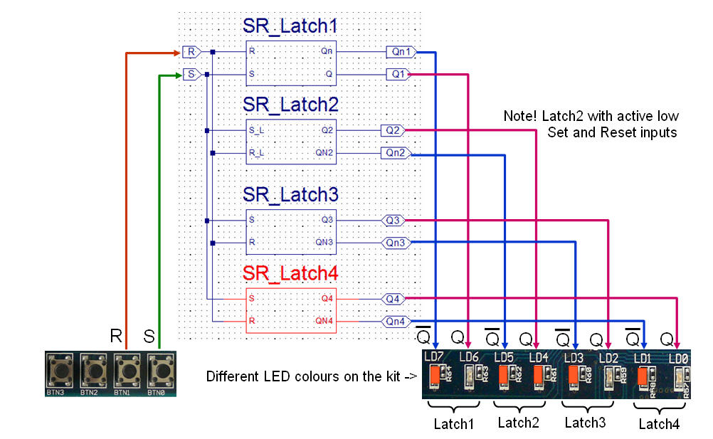
Another useful
implementation of a SR-Latch with NAND-gates.
Note! The Set and Reset now active low.
This circuit also the
basic for the D-Latch and hence the D-F/F
Read more in
Wakerly 4ed - 7.2.2
|
|
|
|
Implementation of SR-Latch
with "pure" concurrent code.
Note! The use of inout
port signal could be avoided with the use of internal signals
(nets)
|
 |
|
|
Implementation of SR-Latch
with a process and hence with sequential code.
In order to simulate this
implementation correct must you fill out the sensitivity list
with all signals found at the right side of the expressions.
Note! The use of inout
port signal could be avoided with the use of internal signals
(nets).
|
 |
| |
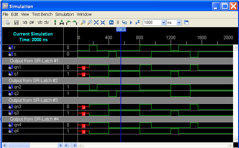
The simulation below shows
how SR-Latch1, Latch3 and Latch4 undefined at start while Latch2
got two active signals as inputs.
In practice will all Latches have a known output from start as
it can test with the bit-file and the kit.
|
 |
| |
|
|
 |
| |