[Home] [#5.1 Counters] [#5.2 Multiple Clock] [#5.3 Ringcounters] [#5.4 LIFO Stack] [#5.5 Rotary Encoder] [#5.6 SPI and UART] [#5.7 PWM vs. Sigma-Delta] [#5.8 ADC with FPGA] [#5.9 Shiftregisters (Sig vs Var)] [#5.10 Rising Falling trigged]
#5.5 Rotary Encoder
Up ]


Rotary encoders also know as Quadrature Encoders


Note!!!!  How the PmodENC should be connected (watch the flower - and the "missing" flower)


Ideal and "real-life" encoder signals


Example of an Asynchronous filter for the Encoder (S-R latch based)

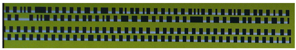
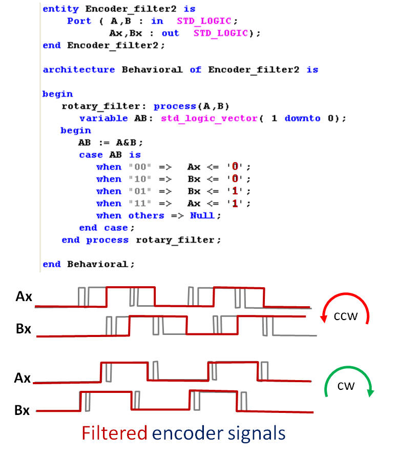
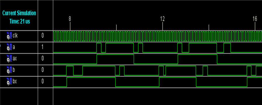
In real-life encoders, specially the ones based at mechanic switches, will bouncing appears each time a switch open and closes.  (*)

By using the fact that one signal always stable while the other changes states can a simple filter be constructed.

However must we accept some form of delay at least in one direction of turns.

There's also a chance / risk that pulses could be last. which could course problems in some applications.

(*) Due to the laws of Murphy will this not happen if you actually wants' it :-)


Example of an Synchronous filter for the Encoder (D F/F based)

Basically the same logic as for the Asynchronous but now with a clock signal and hence will this force the synthesize tool to use Flip/Flops.

The Clk signal must have a higher frequency then the A and B signals changes.


Example of circuit which detects changes and direction.


  Hit Counter