Some problems calls for
solutions which involves multiple clock signals. Consider a
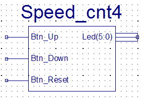
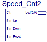
6-bit counter which should react each time one of three buttons
pushed.
<Btn Down>
= <Btn0> Should Decrement the counter with "1"
<Btn Up> = <Btn1>
Should increment the counter with "100"
<Btn Reset> = <Btn3> Should set
the counter to all zeros
|
|
|
|
|
|
|
|
|
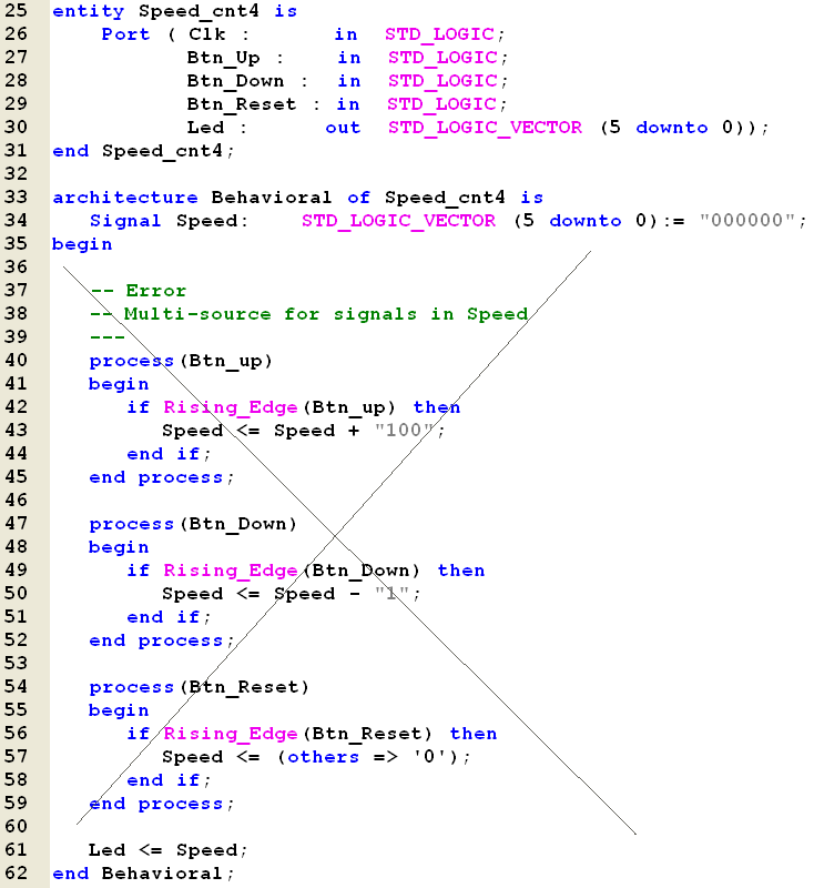 |
Line 26 - The Clk actually not
needed but its here for future-use.
Line 40 - Line
47 - Line 54
There's no problems with the use of Btn_up, Btn_Down
and Btn_Reset as Clock-signal for a process.
Line 43 - Line
50 - Line 57
The problem arises when two or more processes (or
concurrent code lines) try to change the same
signal.
Multiple drivers or Sources will result as a
short-circuit between output in the physical
hardware.
|
|
|
|
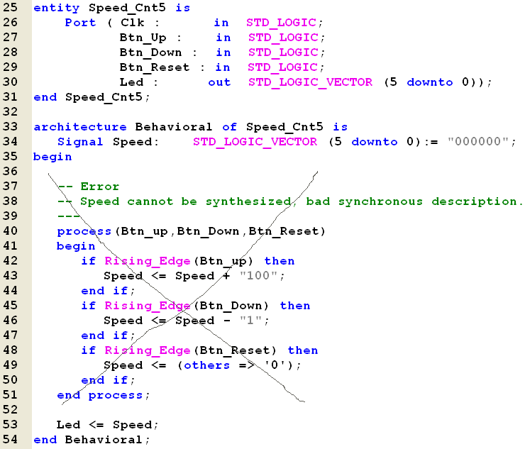
Line 26 -
The Clk actually not needed but its here for
future-use.
Line 42 - Line
45 - Line 48
If your VHDL should be synthesized to "real"
hardware must a process only contain one line with
either
Rising_edge
or
Falling_edge
calls.
If your writing
code for simulation will it be okay to include
multiple edge-sensitive statements.
Note! FPGA will
typically contain F/F which could used as positive
(rising) edge F/Fs or negative (falling) edge ditto.
New types of
CPLD's present F/F's which could trigged at both
rising edge and falling edge of the Clock signal.
What's the big
idea between that feature???
|
 |
|
|
|
|
|
 |
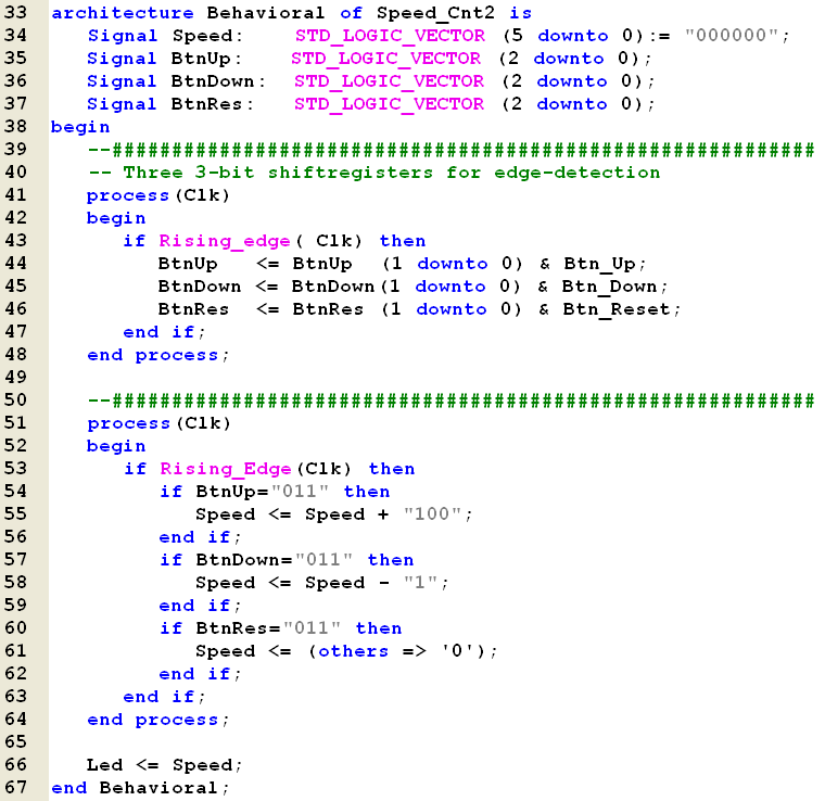
Line 35 .. 37
Defines three shift registers of each 3-bit length.
The process at
line 41 .. 48 shift the respective Btn
signals into the registers.
000 = Button not
pressed.
001 = Button now pressed
011 = Button still pressed
111 = Button pressed (for a long time)
110 = Button
released
100 = Button still released
000 = Button not pressed
010 = Example of bouncing
101 = ditto
For each rising
edge of the Clk will the Shift Registers be
checked for valid "Button presses" defined as "011"
|
 |
|
|
|
|
|
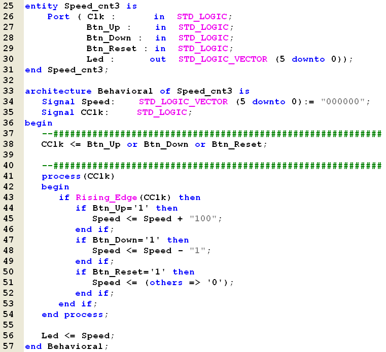 |
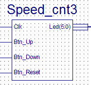
Line 38 - The CClk signal will be '1'
when ever one of the three Btn signals
changes to '1'.
This solution will
surely give Yellow ! signs telling about the danger
of "Gated Clock".
What could go
wrong then???
Normally will a
problem arise if Data arrives too early to F/F and
before the Clock signal.
However seems the
opposite to be problem here. A press at the <Btn_Down>
produces a CClk but the signal arrives to
late in order to be detected at the logic created by
line 47..49
TRY IT
YOURSELF!
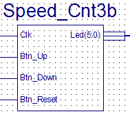
If the lines
43..46 and 47..49 changes places will a
better logic be generated and the count down
functionality works again.
|
|
|
|
|
|
 |
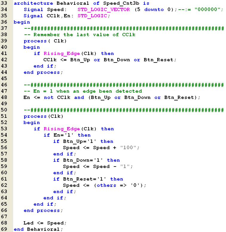
The alternative to
gated clock includes the use of a Clock Enable
signal.In
order to produce an active "En" signal for
one clock period must a single F/F hold the CClk
signal for one Clk-period.
When ever CClk='0' and one of the three
Btn signals '1' will the En change value
to '1' as well.
The next rising
edge at the Clk signal will then allow
line 55 .. 63 to be active thanks to En='1'
and line 54.
The very same
rising edge will also "turn off" the En='1'
by setting CClk='1' in line 42.
|
 |
|
|
|
|
|
|
|
|
|
|
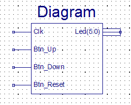
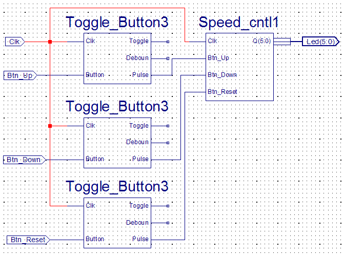
Please note!
The Pulse signal will be
high for one clock-period. It should be used as
Clock-Enable signal and hence is it important that
both circuit (Toogle_Button3 and Speed_Cnt1) are
driven with the same Clk-signal.
|
|
|
|
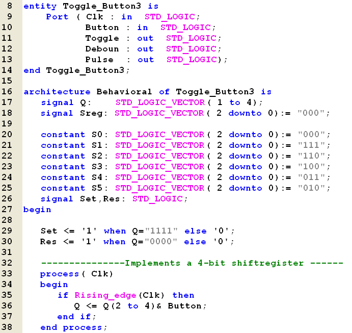
Toggle_Button3
It seems very difficult
(for me at least) to use manually coded states with
the StateCAD tool of the ISE-package.
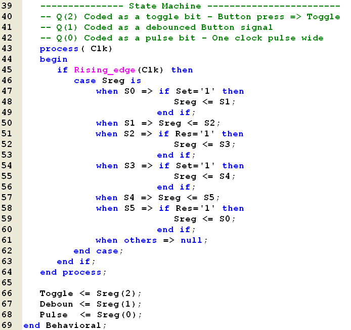
Line 20 .. 25:
An optimal solution for a State Machine which can
debouche a signal (with a 4-bit shift register
named Q in line 17) and produce a Toggle-output, a
Pulse-output and a Debouched-output will always be
direct coding of the output-values into the states.
Line 29 + 30
In order to build in Hysteresis will the Set only be
active after four 1-bit in a row - in contrast to
the Res which requires four 0-bit in a row to be
active.
|
 |
| |
 |
|
|
|
|
|
