The Task
- Create a
logic circuit with the following functionality:
There should be two
data inputs A,
B (plus a Clock
signal ?) + one output: F = f(
A, B)
If
A=1 and
B=1 then
F =
A and B
until A=0 and
B=0
If A=0
and B=0
then F
= A
or
B until
A=1 and
B=1
|
|
|
One way to document a sequential circuit
could be a "horizontal truth table" which shows the output
F as a function of time and the
inputs (A,B)
Please note the need of showing the (internal) states: OR - AND
|
 |
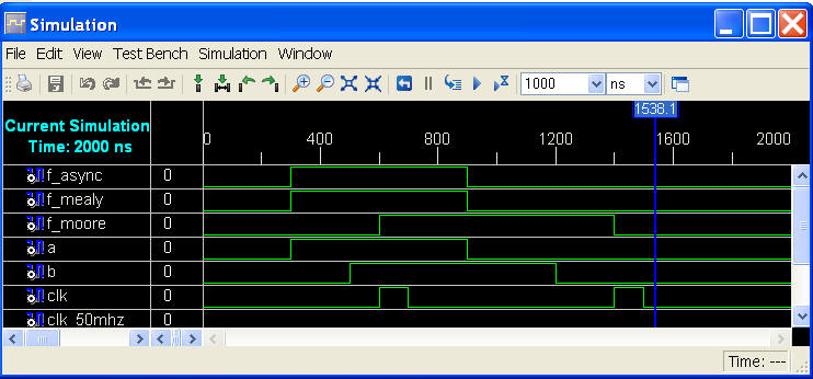
The waveform display can also be seen as a
"real-life" presentation as this can be seen with a logic analyser.
|
 |
|
|
The most popular graphical way
to document a Sequential system called State Diagrams.
Each State should be given a
name or number and the transitions between states shown with arrows
and their input conditions.
Moore outputs depends only at
the state.
Mealy outputs depends at both
state and input.
|
 |
A state table just another way
to present states, conditions and transitions.
Compare the State diagram
above with the Table.
|
 |
|
|
In order to actually implement
a Sequential circuit with logic must all states be converted into
binary numbers.
The case with two states kind
of easy, since it can be done with only one bit.
|
 |
|
|
The design and
implementation of Asynchronous feedback loops (in Async. State
Machines) not a task for beginners and even profs will have a
hard time doing it, hence the ISE-tools not meant for this.
|
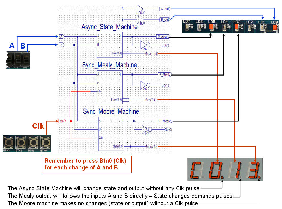
This Ad-hoc Asynchronous
design will work in practice as its kind of simple.
The state memory formed by a
SR-Latch, which controls a multiplexer.
The Set-signal
activated when A=1 and
B=1.
The Reset-signal
activated when A=0 and
B=0 (a NOR function)
|
 |
|
|
Instead of watching the input
signals (A, B)
continually as for the Asynchronous circuit will it be easier to
create a circuit which only "evaluates" the signal at certain times,
controlled by a Clk signal.
Please note the state changes
follows the Clk (Rising edges)
where as the output signal F
also depends on the input signals A,
B
|
 |
|
|
From the Coded state/Output
(shown above this) can the "Next State equations" be found
The same is true for the
"Output equations"
Try to derive the Equations
yourself and check the State Machine shown here.
IMPORTANT NOTE:
In real-life systems must you avoid random (asynchronous) changes of
input signals (A or B).
The Q output from the F/F's
might go metastable and/or more likely will the state become
undefined due to timing-hazard.
SOLUTION: Use a
Synchronisation F/F for each input.
|
 |
|
|
The alternative to
Mealy-outputs called Moore-outputs.
(MOOre depends
on State Output Only)
Study the State/Output table
shown at the right and draw the equivalent State Diagram.
How come we now need four
states instead of two?
|
 |
| |
|
|
|
How many Flip/Flops needed for
the coding of this state machine?
How many ways (combinations)
do you have to choose among when coding the state machine?
|
 |
Why seems this coding to be a
better solution?
|
 |
| |
| |
 |
| |
 |
 |
| |
| |
 |
 |
| |
| |
 |
 |
| |
| |
 |
| |
| |
 |
| |
|
|
|
 |
| |
|