[Home] [Why ...] [Boolean algebra] [Carnaugh Maps] [AND-OR-NOT] [Number Systems] [Combinatorial logic] [Sequential logic] [State-Machines] [Examples]
State-Machines
Up ] Async. vs. Sync ] State Diagrams ] VHDL implementaions ] Levels of abstraction ] Kiss to FSM ]


Last updated: 15-02-09

 
        State Diagrams / Design


Almost all digital electronic of importance based at the principle of the Synchronous State Machine - SSM or Final State Machine Machine - FSM.
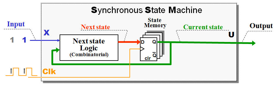
The State Memory enables the FSM to remember what happened in the past - The output from the F/F's referred as Current state.

The Next State Logic (pure combinatorial) decide what should happens next - This decision done by looking at Inputs and the Current state. 
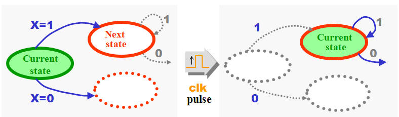
The output from the Next State Logic called Next State (of course) and is just waiting for the next rising edge clock pulse to become a new Current state.

The Current state could be used directly as output (Output coded states) but could be transformed through combinatorial logic


Part of a State Diagram - a common way to document a State Machine


Transitions Table
Current
state
X = 0 X = 1
 0 0 0 0 0 0 0 0 1
0 0 1 0 0 1 0 1 0
0 1 0 0 1 0 0 1 1
0 1 1 0 1 1 1 0 0
1 0 0 1 0 0 1 0 1
1 0 1 1 0 1 1 1 0
1 1 0 1 1 0 1 1 1
1 1 1 1 1 1 0 0 0

  Next state             

Several methods for Design, Description and Synthesising of State Machines can be found in textbooks and on the net.

The old methods not really used nowadays, but they do have interest in order to understand the principles inside a SSM.

The Transitions Table one step in the process of achieving the Exatations Equations for the Next State Logic.


Hit Counter