|
|
| |
State Diagram Design - a
Method
|
Last updated:
01-02-09 |
The design of State Machines
the most creative process you might experience - compared with
the task of software design.
When it comes to deriving the Boolean equations its more like
"turning the crank" (Wakerly 4ed page 554)
|
|
|
State Diagrams and State Machines |
| |
|
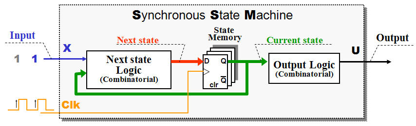
Almost all digital electronic of importance based at
the principle of the Synchronous State Machine - SSM
or Final State Machine Machine - FSM.
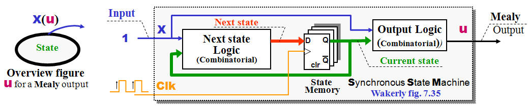
The
State Memory
enables the FSM to remember what happened in the
past - The output from the F/F's referred as
Current state.
The
Next State Logic
(pure combinatorial) decide what should happens next
- This decision done by looking at Inputs and the
Current state.
The output from the
Next State Logic
called
Next State
(of course) and is just waiting for the
next rising edge clock pulse
to become a new
Current state.
The
Current state
could be used directly as output (Output coded
states) but could be transformed through
combinatorial logic.
|
| |
|
| |
 |
| |
|
|
 |
|
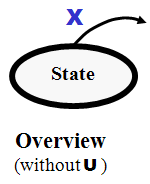
In
order to document the functionality of a FSM / SSM
will State Diagrams often be the best choice. Each
state represented by a circle (or ellipse) and the
graphics describe the possible states and the
transitions between.
Note!
The idea behind states and State Diagrams not only
applies digital hardware - You might consider using
states while writing software as well. In fact
can most of our daily activities be described with
State Diagrams (But don't try it)
|
|
|
|
|
|
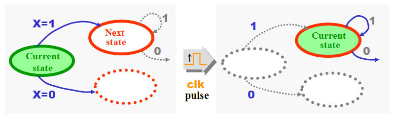
State Machine with Moore output |
| |
|
 |
| |
|
| |
 |
| |
|
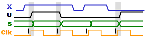
If the Output from
a State Machine only depends at the Current state is
it a Moore output - Hence will all changes at the
output be synchronous with the Clock pulses.
|
| |
|
|
|
State Machine with Mealy output |
| |
|
 |
| |
|
| |
 |
| |
|
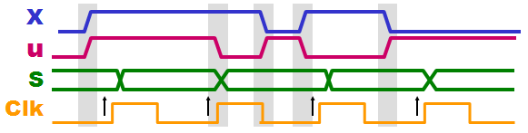
If the Output from
a State Machine depends at both the Current state
and the inputs is it a Mealy output - Hence could
some changes at the output follow changes at input
signal. Please note! if you got a State Machine with
say 100 states and the 99 states got output that NOT
affected by input changes (Moore output) but i a
single state a Mealy type, then the whole State
Machine a Mealy State Machine.
Asynchronous
changes inside a Synchronous systems calls for
problems (read! Metastability and Hazards), but
nevertheless could a Mealy output be the best
solution.
|
| |
|
|
|
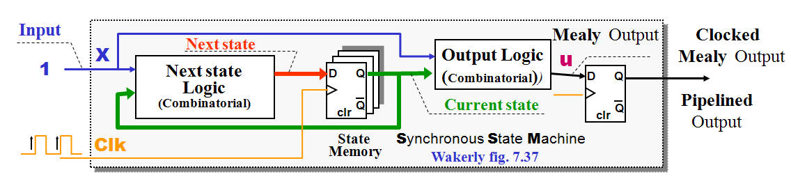
State Machine with Clocked Mealy output
(pipelined) |
| |
|
 |
| |
|
In order to
synchronize a Mealy output could it be necessary to
add an extra F/F, which solves the problem but also
add extra delay.
|
| |
|
|
|
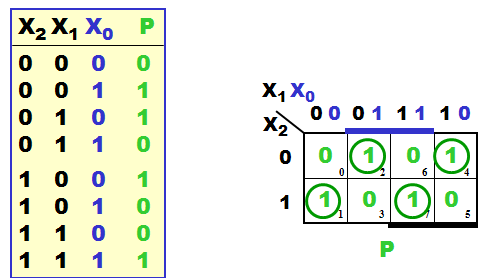
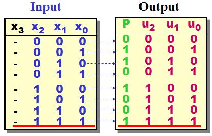
3-bit Parity generator -
Combinatorial logic |
| |
|
Parity often used
in connection with serial communication and storage.
If data given at parallel form would a combinatorial
design be the most natural and best solution.
|
 |
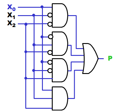 |
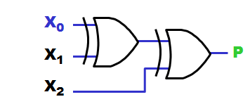
A parity generator
implemented with "pure" AND-OR logic will normally
be a costly solution.
Whenever your Carnaugh-map looks like a chessboard
should you consider using XOR gates, and if you can
accept a modular design could the cost of logic
gates be minimized.
|
| |
 |
| |
|
Consider your
about to implement a 8-bit Parity generator with
"pure" - NAND-NAND logic (one level only). How many
gates - with how many inputs do you need (forget the
inverters for the inputs) ?
|
Answer - hold
down the left mouse button and drag:
8-bit = 256
combinations and half of then must produce an
output = 1, hence must we have 128 NAND gates
with 8 inputs and finally one NAND gate with 128
inputs.
A similar
modular design with XOR gates will only cost 7
XOR gates with 2 inputs each.
|
|
|
3-bit Parity generator -
Sequential logic (State Machine) |
| |
|
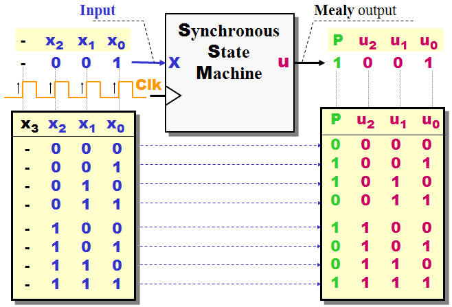
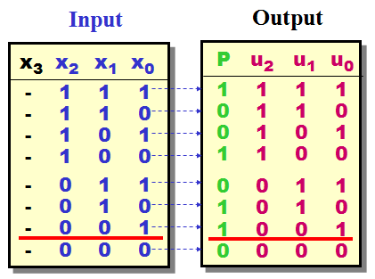
If data given as a
stream of bits (serial form) could the best
solution for a Parity generator be a Synchronous
State Machine.
Please note that the serial stream "stuffed" with an
empty bit space X3
- The SSM will then fill in the
Parity
bit
once generated
|
| |
 |
| |
|
|
|
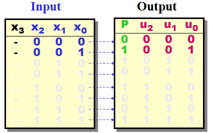
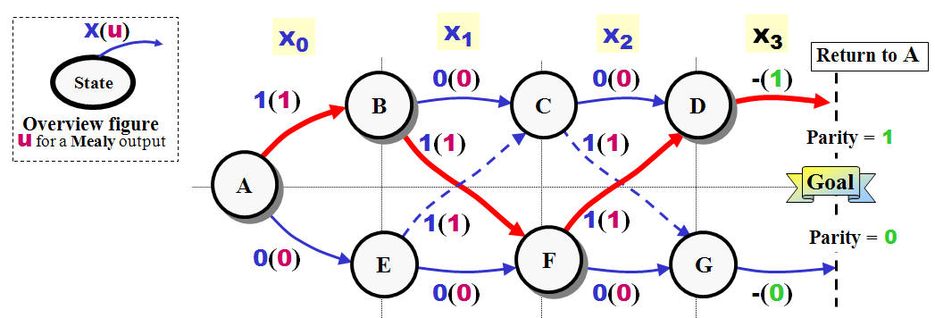
State Diagram for the sequential
3-bit parity generator ("lazy"
solution) |
| |
|
 |
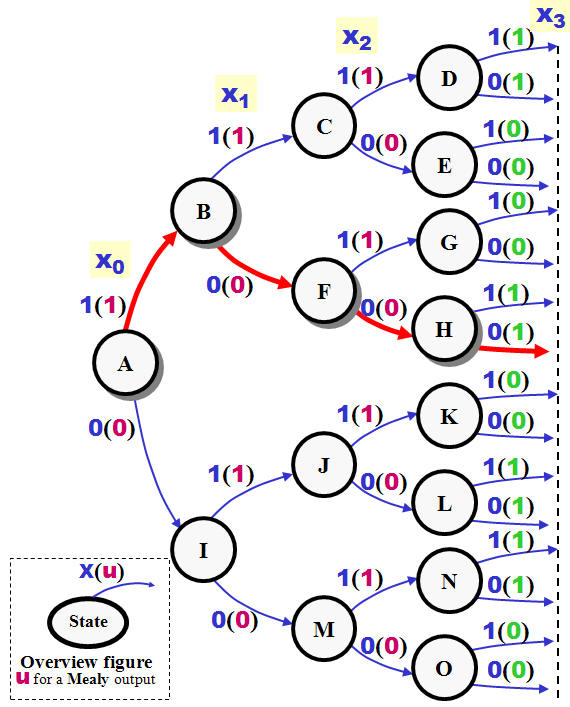 |
One characteristic for a Final State
Machine is a final number of states :-)
You could start a
design by drawing a State Diagram like the one shown
at the right, and - yes the number of states final,
but the solution not optimal.
You could find
methods for reducing the number of states at the net
and in advanced textbooks.
BUT - hardware
cheap nowadays and hence should you put the effort
in making a State Diagram which easy to understand,
maintain and implement instead of saving a F/F or a
gate somewhere.
|
| |
|
|
|
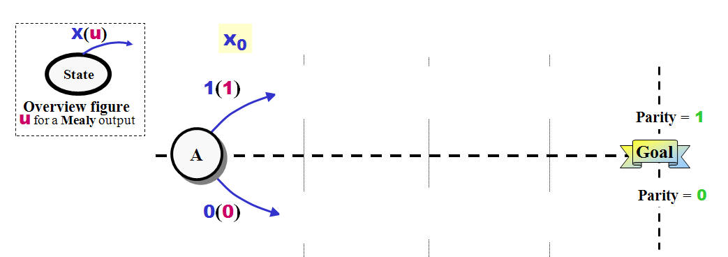
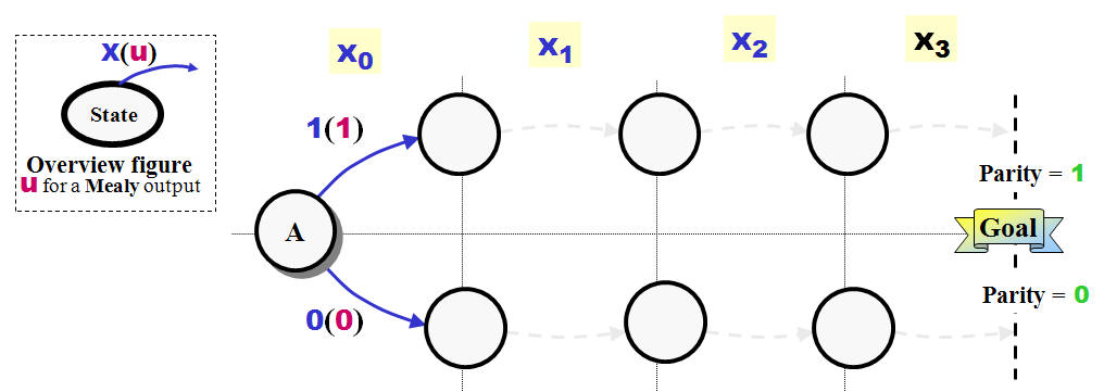
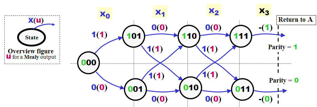
State Diagram design -
choosing a strategy |
The rules below not a
solution to every problem you might face - drawing
State Diagrams as every problem call for its own
special solution:
-
Draw
an overview figure - How many input / outputs
needed and would they be Mealy or Moore types.
-
All State Machines need a state to start - this
might as well be an IDLE state. Draw the state
and give it a name - say
A
if you can't find any better.
-
Decide the
Goal
or goals for your State Diagram
/SSM.
In this case will it be a
Parity
bit equal
1
or
0.
|
 |
 |
| |
|
|
|
State Diagram design -
getting
started |
| |
|
-
Decide how many
clock pulses (minimum) it will take to reach
your goals. You might draw empty state circles
to indicate the paths.
|
 |
 |
| |
|
|
|
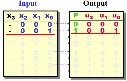
State Diagram design -
the strait
paths |
| |
|
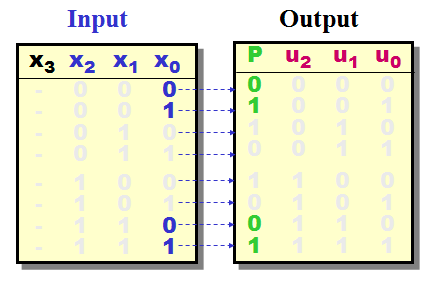
-
This one the most
important - If you about to create a State
Diagram which should recognize some kind of code
- then you should start expecting that this
combination of bit arrives just like you wants
them.
In case of the Parity generator should you
choose the combinations 000 and 001 which lead
to
Parity
0
and
1
|
 |
 |
| |
|
|
|
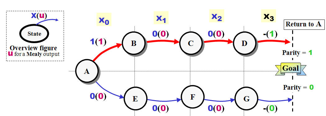
State Diagram design -
filling out
the gaps |
| |
|
-
For each state
which still missing transitions lines or where
the transitions might be "undefined" due to
ambiguous conditions must you consider what to
do next.
First must you try "re-cycle" the states already
defined.
This surely the case here - as the
Parity
changes between
0 and
1 each time a new high
value accepted as input.
But in other - real life designs - must you
properly add extra states in order to handle
special cases.
-
Fill out the
State diagrams with the missing transitions and
your done.
|
 |
 |
| |
|
If your planning
to use VHDL for the implementation and settles for
enumerated state assignment your ready to go now.
The setup of your ISE, choice of Hardware CPLD /
FPGA and the amount of state will either select a
binary coding or a one hot style.
But just for the
example - lets take
the full Monty :-)
|
| |
|
|
|
State Diagram design -
State Coding |
|
|
Why is One Hot
so hot for a FPGA?
Lets consider
a State Machine with 33 states - with a binary
code style will you need 6 F/F's while a One Hot
code style will cost you 33 F/Fs - how could
this be an advantage !!!!
First must you
realize that the amount of F/Fs available inside
a FPGA quite high - how ever are the
combinatorial resources short (if the number of
required input above 4 - since a Look Up Table
takes four in and give one out)
If you analyze
State Diagrams will you find that's the number
of transition arrows leading to a state seldom
above 2 - meaning that the Next State logic for
this state could have two inputs together with
the two "hot bits" and still fit inside a LUT.
If your instead insist of using a Binary code
will you have to consider 2+6 bits for the Next
State logic.
|
|
|
|
With 7 states, how
few Flip/Flops needed to implement this State
Machine?
|
Answer:
23
= 8 possible states - you need 3 F/Fs
|
How many possible
combinations of state coding do you have?
|
Answer:
8! =
8*7*6*5*4*3*2*1 = 40320 combinations
|
| |
|
 |
| |
|
| |
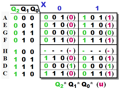 |
Of all the
combinations possible I do believe the chosen one
also the best. Check the State Transitions Table at
the right.
What's the idea
behind this state coding?
|
Answer:
In order to keep
track of the number of X-bits arrived we surely need
a counter - Hence is Q1 and Q0 coded as a 2-bit
ditto.
The most
significant bit holds the parity value at the give
state.
|
| |
|
|
State Machine design - "Turning
the Crank" |
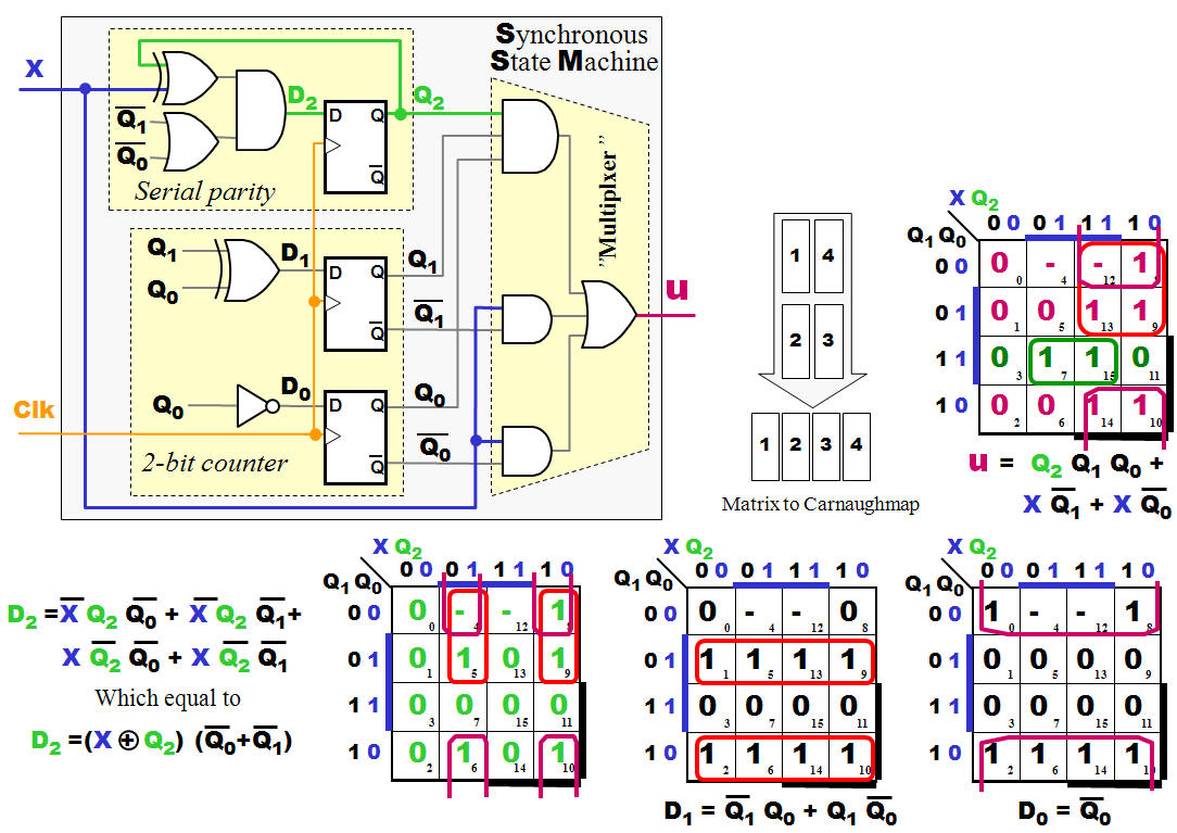 |
Conclusion:
|
|
After a bit
bit-manipulation, could the Boolean Equation for the
Next State logic and the Output Logic be derived.
Big surprise - it seems we got what we asked for:
- A
two-bit counter to keep track of the number of
bits arriving.
- A
circuit which generates a Serial Parity (please
note the OR-gate - What's the purpose of this?)
-
-
Finally will the Mealy output come from a
Multiplexer which either select the input
X
direct or the
Parity bit.
If you where asked
to create a 16-bit Serial Parity Generator, how
would you solve this task?
|
|
|
 |