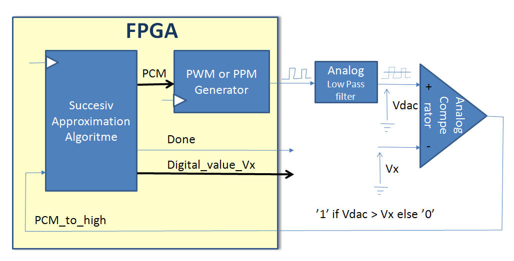
[Home] [#5.1 Counters] [#5.2 Multiple Clock] [#5.3 Ringcounters] [#5.4 LIFO Stack] [#5.5 Rotary Encoder] [#5.6 SPI and UART] [#5.7 PWM vs. Sigma-Delta] [#5.8 ADC with FPGA] [#5.9 Shiftregisters (Sig vs Var)] [#5.10 Rising Falling trigged]
#5.8 ADC with FPGA
Up ]


Normally will a FPGA not be able to handle analogue signal (The Fusion FPGAs from Actel an exception from this rule)

However will it be possible to generate an analogue output signal in form of a PWM or PPM signal (one bit). With the help of an analogue low pass filter will the Vdac be useful for comparison with an unknown voltage Vx.


  Block diagram of an ADC implementation with a FPGA and external components


The Successive Approximation Algorithm:


The best way to present this algorithm will be the game High Low (which could be found at the TI95 calculator)

Think of a number between 0 and 255 - it now my task to guess this number by guessing a number and you must tell me if the number is High or Low.

"Secret" number = 189

My first guess = 128    => your answer to Low      (128 = 1000.00002)
My next guess = 192   => your answer to High     (192 = 1100.00002)
My next guess = 160   => your answer to Low      (160 = 1010.00002)
My next guess = 176   => your answer to Low      (176 = 1011.00002)
My next guess = 184   => your answer to Low      (184 = 1011.10002)
My next guess = 188   => your answer to Low      (188 = 1011.11002)
My next guess = 190   => your answer to High     (190 = 1011.11102)
My last  guess = 189   => your answer to OK       (189 = 1011.11012)


  VHDL implementation of ADC in FPGA
 

Yet to come .....


Hit Counter